A repetitive array of diffracting elements, either apertures or obstacles,
that has the effect of producing periodic alterations in the phase, amplitude,
or both of an emergent wave is said to be a diffraction grating. One of the simplest
such arrangements is the multiple-slit configuration. It seems to have been invented by
the American astronomer David Rittenhouse in about 1785. Some years later Joseph von
Fraunhofer independently rediscovered the principle and went on to make a number of important
contributions to both the theory and technology of gratings. The earliest devices were indeed
multiple-slit assemblies, usually consisting of a grid of fine wire or thread wound about and
extending between two parallel screws, which served as spacers. A wavefront, in passing through
such a system, is confronted by alternate opaque and transparent regions, so that it undergoes a
modulation in amplitude. Accordingly, a multiple-slit configuration is said to be a transmission
amplitude grating. Another, more common form of transmission grating is made by ruling
orscratching parallel notches into the surface of a flat, clear glass plate.
Each of the scratches serves as a source of scattered light, and together they
form a regular array of parallel line sources. When the grating is totally transparent,
so that there is negligible amplitude modulation, the regular variations in the optical
thickness across the grating yield a modulation in-phase, and we have what is known as a
transmission phasegrating. In the Huygens–Fresnel representation you can envision the wavelets
as radiated with different phases over the grating surface. An emerging wave front therefore
contains periodic variations in its shape rather than its amplitude. This in turn is equivalent
to an angular distribution of constituent plane waves. On reflection from this kind of grating,
light scattered by the various periodic surface features will arrive at some point-P with a
definite phase relationship. The consequent interference pattern generated after reflection
is quite similar to that arising from transmission. Gratings designed specifically to function
in this fashion are known as reflection phase gratings. Gratings of this sort
have traditionally been ruled in thin films of aluminum that have been evaporated onto
optically flat glass blanks. The aluminum, being fairly soft, results in less wear on
the diamond ruling tool and is also a better reflector in the ultraviolet region.
In actuality, most gratings are exceedingly good plastic castings or replicas of fine,
master ruled gratings.
Today, large numbers of gratings are made holographically.
Recall the analysis and the expression \(a \sin\theta = m \lambda \) which is known as
the grating equation for normal incidence. The values of m specify the order of the various
principal maxima.
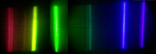
For a source having a broad continuous spectrum, such as a tungsten filament,
the m = 0, or zeroth-order, image corresponds to the un-deflected,
\(\theta_{0} = 0\), white-light view of the source.
The grating equation is dependent on l, and so for any value of m Z 0
the various colored images of the source corresponding to slightly different angles (\(\theta\))
spread out into a continuous spectrum.
The regions occupied by the faint subsidiary maxima will show up as bands seemingly
devoid of any light.
The first-order spectrum m = ±1 appears on eitherside of \(\theta = 0\) and is followed,
along with alternate intervals of darkness, by the higher-order spectra, m = ±2, ±3…
Let us now examine in some detail a few of the major features of the grating spectrum.
Assume an infinitesimally narrow incoherent source.
The effective width of an emergent spectral line may be defined as the angular
distance between the zeros on either side of a principal maximum; in other words, \(\Delta \alpha = \frac{2\pi}{N}\)
, w. At oblique incidence we can redefine a as \(\frac{ka}{2}\sin\theta - \sin \theta_{1}\),
and so a small change in a is given by
$$ \Delta \alpha = \frac{ka}{2} \cos \theta, \Delta \theta = \frac{2\pi}{N} $$
where the angle-of-incidence is constant, that is, \( \Delta \theta_{i} = 0 \).
Thus, even when the incident light is monochromatic,
$$ \Delta \theta = 2\lambda l Na \cos \theta m $$
is the angular width of a line, due to instrumental broadening.I
nterestingly enough, the angular linewidth varies inversely
with the width of the grating itself, Na.
Another important quantity is the difference in angular position
corresponding to a difference in wavelength. The angular dispersion, as in the case of a prism, is defined as
$$D = \frac{d\theta}{d\lambda}$$
Differentiating the grating equation yields
$$D = ml(a \cos \theta m)$$
$$R = Na \frac{\sin \theta}{\lambda}$$
The resolving power is a function of the grating width Na, the angle-of-incidence,
and \(\lambda\). A grating 6 inches wide and containing 15,000 lines
per inch will have a total of 9 * 104 lines and a resolving power,
in the second order, of 1.8 * 105 .In the vicinity of 540 nm,
the grating could resolve a wavelength difference of 0.003 nm.
