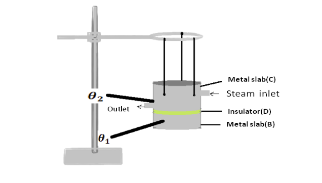
Lee's disc apparatus
The given bad conductor (D) is shaped with the diameter as that of the circular slab B. The bad conductor is placed in between the steam chamber (C) and the disc (B), provided the bad conductor, steam chamber and the slab should be of the same diameter. Holes are provided in the steam chamber (C) and the disc (B) in which thermometers 1,2 are inserted to measure the temperatures.The total arrangement is hung over the stand as shown in Fig1.
The rate of heat loss = \(\frac{dQ}{dt}=Mc\frac{d\theta}{dt}\)
\(M\)- Mass of disc
\(C\) – specific heat capacity of disc
\(\frac{d\theta}{dt}\) - temperature loss per unit time in \(\theta_2\)
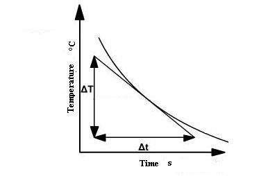
Note : \(\frac{d\theta}{dt}\) can be measured from cooling curve . It is slope of cooling curve of disc B.
\(A\) – area of bad conductor
(\(\theta_1\)- \(\theta_2\)) - temperature difference in steady state
\(L\) – thickness of poor conductor Equating both equations
Thermal conductivity = \(k = \frac{M×c×L×\frac{d\theta}{dt}}{A×(\theta_2-\theta_1)}\)